Inlets, Manholes and Pipe Layout - Completely Intuitive
The workflow for laying out Inlets, Manholes and Pipe Networks is pretty much intuitive:
The Reference Elevation for Inlets and Manholes is the Top (Rim, Throat, or Cover).
Before Conduits are attached to the Junctions (Inlets or Manholes), they have a default depth (called Default Height).
When laying out conduits, you will note that there is no prompt for invert elevations of the pipe. Some default elevations are assumed.
The underlying assumption is that it is proposed system: a series of constraints will be applied at Design Time and the inverts of the pipes assigned then.
For pipes, this works completely intuitively. Pipes are lowered to meet minimum cover and slope requirements, etc.
(over 15 design considerations are balanced during Design (link))
Headwalls, Cross Section Nodes and Channels: a little more complicated
Layout for Channels bifurcates: there are two scenarios and they have different needs. Currently there is one behavior. Both scenarios are actually handled well in current internal builds of the software. When released, both scenarios will have clean, streamline workflows.
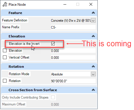
The current challenge is: what does the Elevation Reference apply to? Top or Bottom? For manholes and inlets in a pipe network, the Terrain always ALWAYS relates to the Inlet Grate Elevation and the Manhole Rim Elevation. It NEVER relates to the structure Invert.
For Channel Workflow we most often use Headwalls and Cross Section Nodes.
Q: Does the Terrain relate to the top or the bottom of the structure?
A: It depends.
|
If you have a Terrain that DOES NOT model a channel, you want the Terrain to model the TOP of the Node. If you have a Terrain that DOES model a channel, you want the Terrain to relate to the BOTTOM of the Node.
In an imminent release, this choice is presented at Layout. All will be Good. |
 |
In the current release,
- the Elevation take from the surface (or typed in) is assigned to the Top of the Structure.
- The Structure has a Height.
- The Invert Elevation is calculated as Top Elevation minus Structure Height.
This is fine for "proposed" channels that do not exist in the terrain. The invert of a channel should be the terrain minus the depth of the channel.
For channels that are already in the terrain, this is less fine. You do want the invert of the channel to be at the terrain.
In this case, you will need to manually adjust the inverts of the channels, when they get attached.
There are some bulk methods to adjust the inverts.
- FlexTables of Channels can adjust inverts by some number (+2.5 ft, for example) either globally or on the results of a query.
- There is a way to use negative cover values (equal to the channel height). During a Design, the software will then move the channel inverts to the terrain.
A final complication when using a Design Computation to adjust inverts. You will need to set the Minumum Cover Values of Channels separate from Pipes. This is done by setting the "Set Local Pipe Constraint?" to True in the Channel Prototypes (described here: Channels and Default Design Constraints)