The simplest way to reference graphics external to the active file is to
- Select the Reference Attach tool.
- Select the file(s) to attach (browse to them)
- Pick an Attachment Method:
-
- Coincident World works well for files with proper GCSs attached
- It's a better idea to use the Interactive method , because you can select the intended model, not the default one.
This is perfect for referencing in the entire reference file.
In many cases, you'll want to only see a limited region of a referenced file. Think: "I don't want the design extending outside the sheet margins."
If you want to limit the range of the reference file's visibility, you can place a fence, and create a Reference Clip from the fence. The Reference Clip will limit the extents of the reference graphics shown.
That method does not leave a very good paper trail, though.
A higher quality method is to place shapes into the source file (that which will be referenced). Put these shapes on a special level, one that will not plot.
| Repeat the process of referencing the model, but when clipping, use the Element option rather than a fence. | 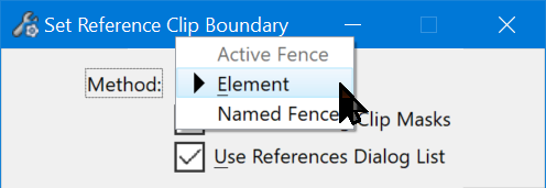 |
Named Boundaries - a Best Practice
OpenRoads is built for automatic updates for MegaProjects. At this scale, "a bunch of shapes" is simply not sufficient to manage referencing for potentially thousands of sheets.
OpenRoads extends an element type called a Named Boundary - it's a shape with lots of properties, including a Name. Named Boundaries are a function in "plain" MicroStation, but OpenRoads extends the properties of Named Boundaries for Civil Engineering AND has functions that are specific to creating these Named Boundaries in bulk for Plan, Profile and Cross Section workflows.
Note: if you are doing "standard" corridor sheeting AND your workspace is properly set up, I recommend you consult the typical available "Drawing Production in OpenRoads" content available at learning.bentley.com or youtube, etc. That material teaches you how to use the automatic functions to get sheets. All is well when it works, but you likely will not understand how things work for custom operations.
OpenRoads Place Named Boundaries tool
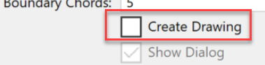
The Place Named Boundary tool can also automatically create Drawing Models from the Boundaries it creates and Sheets from those Drawing Models. Note that this is a bulk process that can create a LOT of models and or files. Many experienced users recommend having the Create Drawing toggle OFF until sure that the Named Boundaries set is "just right".
|
This tool creates named boundaries from multiple methods and can optionally create drawing models and sheets automatically. Civil Plan (icon #1) places rectangular* shapes along a path and makes Named Boundaries of them. The shapes are centered on the path at the ends (they cross the path at the midpoints of the ends). Primary shape factors:
*Boundary Chords allow vertices along the length - to "bend" around curves. Note that there are Drawing Seeds - which are presets of these and other characteristics, including the Detail Scale. Picking a Detail Scale will set the rectangle size; changing the Detail Scale will resize the Length and Offsets accordingly. The essence of this tool is that you get a sequence of Named Boundaries along the path of a size and shape that fits on sheets. Civil Profile is an essential tool to plot Profiles - the dynamic Profile Window Models are NOT shareable or plottable. You MUST create a Profile Drawing Model in order to reference a profile, say, to plot it. The Civil Profile tool allows you to create the rectangular shapes either by Station or by matching the Named Boundaries of a previously-defined Plan set. Civil Cross Sections creates regularly-spaced equal-width Named Boundary rectangles along the selected path perpendicular to the path. Height of the rectangle is based on terrain and found objects in the section. The way to get different spacing or width on sections is to run the tool again with the different settings. You can use the Civil Cross Section 2 Points tool to create "one-off" sections and skewed sections. Note: some geometry you may want to work out ahead of time.
|
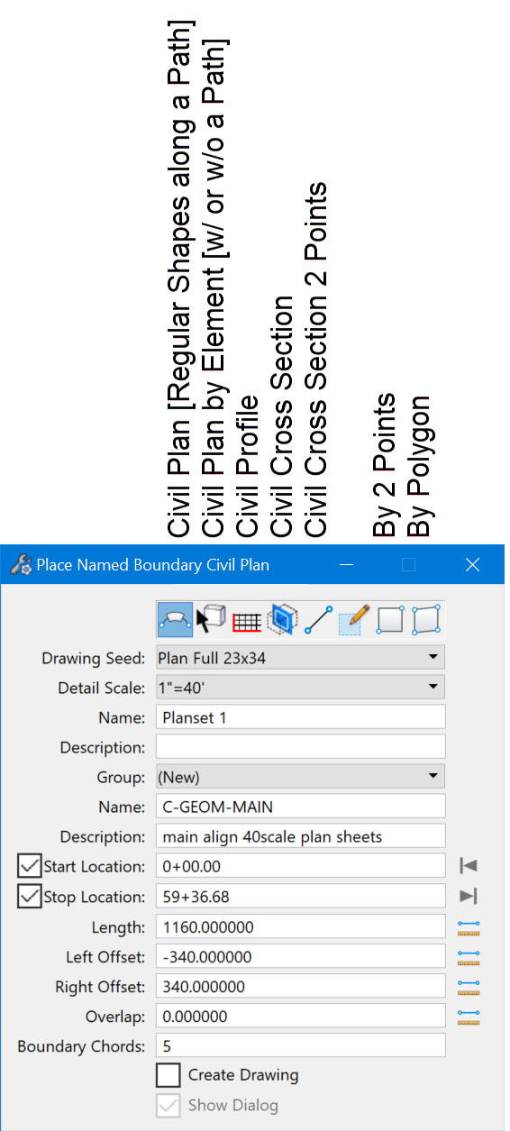 |
Civil Plan By Element allows you to select one or more shapes (regular or irregular) along a pathway. If the pathway moves, the Named Boundaries move with it.
The By 2 Points and By Polygon turn on-the-fly shapes into Named Boundaries. They are static, not connected to a pathway.
|
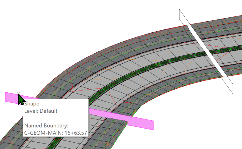
With Create Drawing off, the result of this tools is a bunch of logically-sorted and well-named Named Boundaries. |
|
Here's an example of how OpenRoads organizes its Named Boundaries:
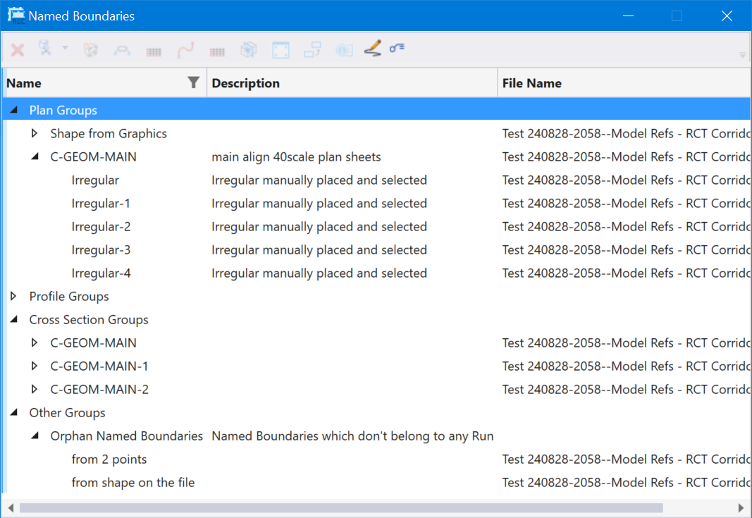
From Named Boundaries we can create Drawing Models and Sheets - see: Drawings and Sheets from Named Boundaries