Hydraulic Pond Design in ORD
Dataset: Pond Design Dataset.zip <-- right-click to download
(Pond Grading is here: Pond Templates )
Overview
The Pond Modeling and Design Process:
1. Model Pre- and Post-Development Flows
2. Calculate Required Storage
3. Prepare the Pond and Pond Structures
a. an Outfall structure into the pond
b. a Pond Outfall Structure
c. a Pond Feature (a shape designated to “hold” the hydraulic requirements of a pond (storage characteristics, etc.)
d. a Pipe between the Pond Outfall Structure and the Site Endwall.
4. Adjust Catchment Outflows if necessary
a. If Catchments were routed to a structure that gets pre-empted by a pond:
i. Move the Proposed Catchment outflows from the Site Outfall to the Pond Outfall
5. Connect the Pond Feature to the Network
6. Define the Pond Outlet Control Structure(s)
7. Evaluate and Refine
a. Compute the Scenario
b. Analyze
c. Adjust as necessary
CivilStorm License
Time-varying calculations require an elevated license (CivilStorm or above). This license may or may not be available and may invoke an additional fee from Bentley. Check with your CAD Administrator.
- To activate CivilStorm, click Drainage and Utilities > Tools > License Activation > CivilStorm
Much of the required work can be done with the default StormCAD license, the CivilStorm license is necessary for Computations, Time-varying analysis and some graph functions.
Prerequisites
This “course” is designed to be very lean in going through the software requirements to compute and evaluate Pond Storage to mitigate Post-Development runoff.
It is assumed that the learner is practiced in the science and magic of pond design. We don’t discuss any theory here.
This material assumes that the learner is familiar with OpenRoads Drainage, including Layout, Scenarios and Alternatives, Computations and Analysis.
The Data Files
The purpose of this course is to work through the software concepts quickly. The dataset is designed for clarity and speed, rather than realism.
The existing terrain is as hydrologically simple as it can get: a single basin with no runoff from “off-site”.
A simple raised roadway (normally-crowned, curbed), roughly parallels the terrain clear drainage area delineation with no offsite runoff.
The road is in fill and it does block direct overland flow from the north half of the site.
Terrain - Existing
The existing Terrain dgn references a “source graphics” file containing a handful of 3D elements. Most of those elements are horizontal and vertical offsets from the central feature. A change to the central feature propagates to the remaining features. It’s contrived but flexible.
Roadway and Improvements Files
The engineering files follow best practices, being federated and properly linked.
Terrain – Ultimate/Combined
The Ultimate Terrain is a Complex Terrain with the Roadway and Pad surfaces merged into the existing terrain. If the existing terrain or proposed assets are changed, the ultimate terrain updates automatically. Combined terrains are particularly necessary for the OpenRoads hydrology tools, as they do not operate across multiple terrains.
Drainage File
The Drainage file is set up with an Existing and Proposed Scenario and Existing and corresponding Proposed reference files.
References
For the Existing Scenario, only the Terrain-existing reference needs to be on.
For the Post-Development Scenario, the inverse should be true.
|
|
|
|
Existing |
proposed |


Existing
A square site, with a single drainage basin – draining to the middle bottom.
Drainage Features include a single Catchment (Grass) and a single, connected Site Outfall structure.

Proposed
Referenced roadway, paved lots and an ultimate surface (existing merged with proposed).
Drainage Features include: Catchments (three Pavements (1 Corridor, 2 Pads) and two Grass Catchments (North and South). All drain to the Site Oufall – so that Pre- and Post- runoff curves can be plotted together.

Pre- and Post-Development Curves
All versions of the _Pond Design.dgn havePre- and Post- Scenarios ready
· The Existing Scenario
o The full site runoff is defined by a single Grass Catchment outflowing to the Site Outfall.
· The Proposed Scenario
o Five Catchments (Two Grass and three Pavements) outflow to the same Site Outfall.
Open up and Look Around
Start HERE – or There or There
Rather that start from Square Zero, we’ve skipped that heavy burden.
_Pond Design – BEGIN *.dgn:
· the file has been created from seed
· references attached
· Scenarios and Alternatives set up
· Time-varying Storm Data set up
· (some) Outfall Structures laid out
· Pre- and Post-Development Catchments (Drainage Areas)) defined
_Pond Design - Everything But the Pond Feature.dgn
· this file skips to the “absolute minimum” pond-specific content. Start with this file to work through the steps starting with creating the Pond Feature and network connections.
_Pond Design - xComplete.dgn
· While “working through the process” increases learning retention significantly, sometimes clicking through a completed workflow is sufficient. It’s certainly faster.
Open a Pond_Pond Design*.dgn file
Determine where you want to start.
The step-by-step starts with: _Pond Design – BEGIN *.dgn
If you’re inclined to not work through the exercise, try:
· _Pond Design - Everything But the Pond Feature.dgn
It’s pretty lean.
Recommendations
View Display Rules
Bentley delivers with their workspace a Display Style/View Display Rule called “Drainage Is Active” (or “SU Active Display” in earlier versions). It hides the elements inactive in the current scenario. Hiding elements is always a bit risky. I’ve cleaned things up a bit, giving it a more precise name Drainage Inactive Hidden (and hiding the Inactive Catchments (they were overlooked) and including a Display Style/View Display Rule called Display Inactive Shaded, were Inactive elements are shaded rather than hidden.
Always Know the Current Scenario
Keep the Scenario dialog open and visible at all times.
Ensure that the Post-Development Scenario is Current
|
The Pre- and Post-Development Scenarios should have already been calculated. A common recommendation for unfamiliar files is to Batch process the necessary Scenarios
|
|

Verify that the Hydraulics are Ready
- Launch CivilStorm
- Click Drainage and Utilities > Tools > License Activation > CivilStorm.
- Click on the Site Outfall structure and hover to get the Context Menu
- Click Graph

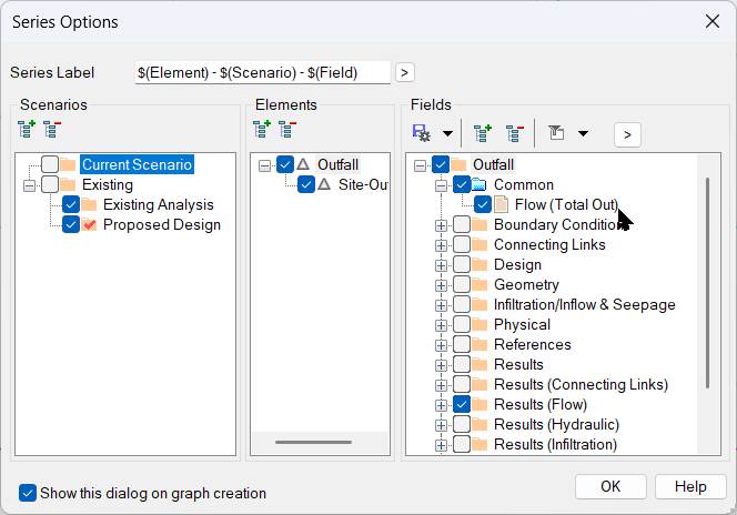
Graphs allow selection of data from multiple Scenarios.
- Select both the Existing and the Proposed Scenarios.
The fields selected by default are specific to the object selected. Flow (Total Out) is what we want here.

- If one or both curves are missing, then Compute the missing Scenario(s).
Prepare for the Pond - Structures
The Proposed Catchments were routed to the Site-Outfall for Pre/Post-Development comparison – primarily to get two curves on the same graph.
In actuality, the post-development rainfall won’t be going straight to the Site Outfall. Ultimately the runoff may travel overland (grass or pavement), in ditches or gutters, through pipes and – because it’s the point here – through a pond.
Post-development runoff is most accurately calculated through its actual collection and conveyance model; but sufficiently accurate estimates can be made with less than the fully-modeled system.
In this exercise we’ll proceed with the minimum requirements (post-development Catchments discharging directly into the pond endwall):
1. an Outfall structure into the pond
2. a Pond Outfall Structure
3. a Pond Feature (a shape designated to “hold” the hydraulic requirements of a pond (storage characteristics, etc.)
4. A Pipe between the Pond Outlet Structure and the Site Endwall
Notes about Pond Features
Note that there is not a tight binding between the 2D shape that becomes an OpenRoads Pond Feature and a Terrain that may include/represent a pond.
If you don’t have a 3D existing or proposed pond, don’t bother creating one. Use an arbitrary shape of any size – the numbers needed for calculation have no requirement to be represented graphically. At all.
Notes about Place a Pond – From Terrain Model
There is a Pond Method option to Calculate the Storage values From Terrain Model. This is excellent if you have a pond grading that is accurate or a “good starting estimate”. The option will read the terrain and provide Elevation-Area values for volume calculations. This is simply a table (a “collection”) stored in the Pond Feature.
There is no “Update Pond Volume from Terrain” tool. If your grading changes, the Elevation-Area values in the Pond Feature must be changed manually.
When iterating a design, there is no hydraulic/calculation advantage to regrading the pond. Just change the values in the Pond Feature table. Once you have a pond geometry numbers that work, then grade the pond as needed.
Place the Pond Endwall
We’ll place an Endwall inside the pond, north side.
- Click Drainage and Utilities > Layout Place Node.
- For Feature Definition, select Generic Endwall.
- It helps to have a clear name. Type Pond-Endwall in Name Prefix and hit <Tab> (to lock in the Name)

- Exact Location and Elevation does not matter much because it will ultimately be adjusted based on the pond grading and any upstream requirements. You can adjust later.
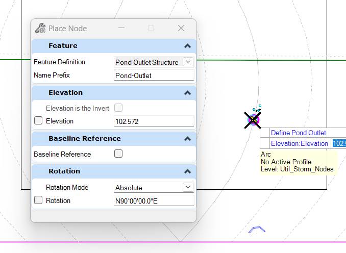
Place the Pond Outlet Structure
We’ll place a Pond Outlet Structure inside the pond, north of the Site Endwall.
|
 |
|
 |
Discharge the Proposed Catchments to the Pond Endwall
The Post-Development catchments are currently discharging to the Site-Outfall. We need to move the discharge to the Pond-Endwall.
This can be done via the Catchment FlexTable or graphically:
- Click on a Catchment to show a line from its centroid to it Outflow Structure
- Hover over the Outflow structure end to show the ReassignOutflow message.
- Click the “handle” over the Outflow.
- Then click on the new Outflow.
|
|
|


A Catchment FlexTable can show the all the Catchments and their Outflow Elements at once.
The Outflow Element can be changed in the FlexTable

Creating the Pond Feature and its Network Connections
The Importance of the Pond Feature Shape
It’s minimal.
We will use an arbitrary shape here rather than a finished 3D pond. Once a Feature, we’ll want to connect the pond to the upstream and downstream networks – so that the software knows where to route the flow.
There is no hydraulic or calculation need for the pond feature’s shape to accurately reflect the pond geometry. If you have an existing pond or a fixed finished pond, then there may be some value in the shape being “accurate”. Note that a pond shape coincident with grading features may make seeing the pond and selecting it slightly more difficult.
The Importance of the Pond Feature
The Pond Feature is required as a data structure to store tables and a Feature to connect to other Features (flow input and output Features).
The pond will need incoming flow from one or more sources (generally, endwalls or outfalls). It will also need an outlet control structure. Pond Outlets are a Drainage and Utilities Feature Definition Structure Type with appropriate attributes and Hydraulic Prototypes.
Pond Outlet Structures
Note that workspaces are often set up with Catch Basins, Endwalls, etc. appearing “straight out of the Standard Drawings” as far as full fine details and perfect geospatial representation. Pond Outlet Structures are out-of-the-box do not show much 3D detail. The infinite variations of control structures make representing them accurately very difficult for little benefit. The hydraulics are never routed though the 3D Structures: it’s all database and math..
Generally a rectangular or circular vault with reasonable spatial dimensions is adequate (approximate width, top elevation and bottom elevation). Top elevations relative to the pond top or berm elevation is useful. Accurate Inverts of Pipes discharging from the structure are important as flow characteristics are calculated for those pipes.
The Layout > Layout > Place Pond tool
This tool has 1 mandatory outcome:
1. creating an OpenRoads Pond Feature with a shape attached to it.
It has two structural selection options:
1. connecting the pond to an upstream discharge
2. connecting the pond to a “downstream” pond outlet structure.
Finally, like Catchments, you have the option of draping the shape to a surface. There is little value to this; select <Alt> to leave it as 2D.
The Pick Points method allows you to define the pond shape on-the-fly with your cursor. 
You will be prompted to select the structure discharging into the pond and the Pond Outfall Structure controlling its discharge. You can select the structures or reject (right-click) to define them later.
|
|
|


.
|
Any Outfall Structure has Boundary Condition settings.
The Boundary Condition Type default “Free Outfall” setting can be changed to Boundary Element and the pond selected. |
|

|
All Pond Outlet Structures have Pond Outlet settings. Upstream Pond, when defined, connects the Pond to the Outlet Structure and the downstream network.
|
|

Click Layout > Layout > Place Pond
|
Follow the prompts to create a Pond Feature. Use the shape in the file or use Pick Points to create your own. If you're feeling bold, try the From Terrain Model method. Not and connect to the inflow and outflow structures (either in the command or via the Utilities Properties dialog). |
 |
A mandatory follow up is to provide some stage/storage (Elevation-Area or Elevation-Volume) information.
- In the Pond feature's Utility Properties, select the Volume Type field, and select Elevation-Area.
This will show the Elevation Area field, which starts with an empty table (a Collection of 0 items),
- click the
 icon:
icon:
Note that the Elevations must be in ascending order. You will get an error upon Compute if not.
|
|

Connect the Pond Outlet Control Structure to the Pond
- Select the Pond Outfall Structure and in the Utilities Properties dialog Pond Outlet settings group, click on the Upstream Pond field:

- Click <Select Upstream Pond>
- Select the Pond Feature in the drawing.
Design the Pond Hydraulics
|
The Pond Outlet Structure Feature has a “doorway to a whole new hydraulic world”: the Composite Outlet Structures dialog
In the Pond Outlet settings group, with Has Control Structure set to Yes, you can select <Edit Composite Outlet Structure>.
|
|

The Composite Outlet Structures dialog is the bulk of hydraulic Pond Design.

It’s a Collection of “Composite Outlet Structures”
Each Composite Outlet Structure is a collection of structures with geometric and hydraulic properties. Multiple structures can exist and be routed in parallel or in series. Each can be renamed.
Ratings Curves can be shown for individual or composite structures (calculated with the Compute button on this dialog)

You can have multiple composite structures defined, but only one is active during a (Scenario) Compute.

CivilStorm supports Interconnected Ponds (varying tailwater). We’ll want Free Outfall here.
Note that Minimum and Maximum Headwater is linked to the Elevations defined in the connected Pond when Use Pond for Headwater Range is selected.
Let's add a Discharge Weir
- Select the Pond Feature.
- Set Has Control Structure to Yes.
- In the Composite Outlet Structure click <Edit Composite Outlet Structure>.
This opens the Composite Outlet Structure dialog.

Define a Weir as the Primary Control Structure
- Click New > Composite Outlet Structure

|
|

|
 |
|
This is where you enter the physical (geometry, elevation, hydraulic) characteristics of the controls structure - in this case a weir.
Flow Direction should be Forward Flow Only.
Ensure that the Type of Weir, Elevation, Length, Coefficient are set.
Note that Downstream ID can be Tailwater or it can be another defined control structure (for serial control).
|
|

Once you have defined your control structure(s), you can "do the math".
Note that CivilStorm's PondMaker tool provides pond sizing and outlet control design guidance. It is fairly complex and outside the scope of this discussion.
Compute, Verify, Refine
Compute
- Hit Compute
(you should have the Scenarios dialog or the Compute Center dialog open (because it's vital to know which Scenario is current (and certain Compute buttons will change the Current Scenario (a bug)))).

The Executive Summary has a Storage tab listing important volume and flow values.
Verify
You can and should have some graphs open to quickly evaluate results.
Discharge Curves
|
 |
The Pre- and Post-Development Discharge Curves are graphed:

Check the Pond
|
 |
Zero Pond Overflow is good!

You can rapidly try different outfall numbers, hit Compute, and see the graphs update automatically.