Hands-on: Use Draping Surfaces to Warp a Parking Lot for Drainage
Engineering Task: Grade a Parking Lot with a Cross Slope and then a warp to ensure positive drainage.
Dataset:: Draping Surface dataset (zip file)
Most Appropriate Pre-requisite: Non-Corridor and Site Modeling course.
Video: Creating the Draping Profiles.mp4
Imagine a fairly straightforward grading requirement, but a complex curbed parking lot with lots of islands and detail work.
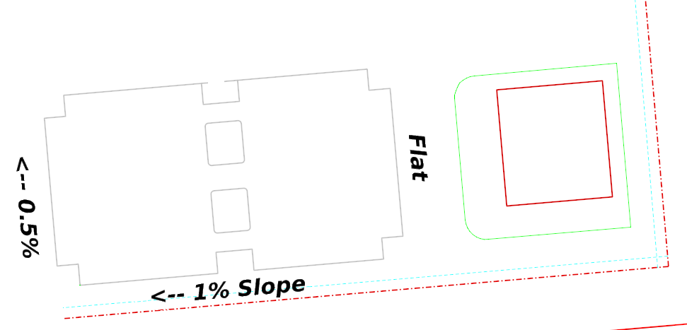
Computing appropriate slopes along each element would be ridiculously difficult. An easy and intuitive technique is to create a "draping surface". The draping surface provides a simple intutive - and easily changed - terrain that design elements get their elevations from.
Create the boundaries of the Draping Terrain.
Since the west and east parking lot edges are parallel to the east boundary line, it is really easy to use an Single Offset tool to define the west and east ends.
1) Click Geometry > Horizontal > Offsets and Tapers > Single Offset Entire.
2) Clear any boxes in the dialog.
3) At the Locate Element prompt, select the East property line.
4) Place the cursor at the east end of the parking lot.
Ensure that AccuSnap snaps to the element. That physical relationship is one we'll want to maintain.
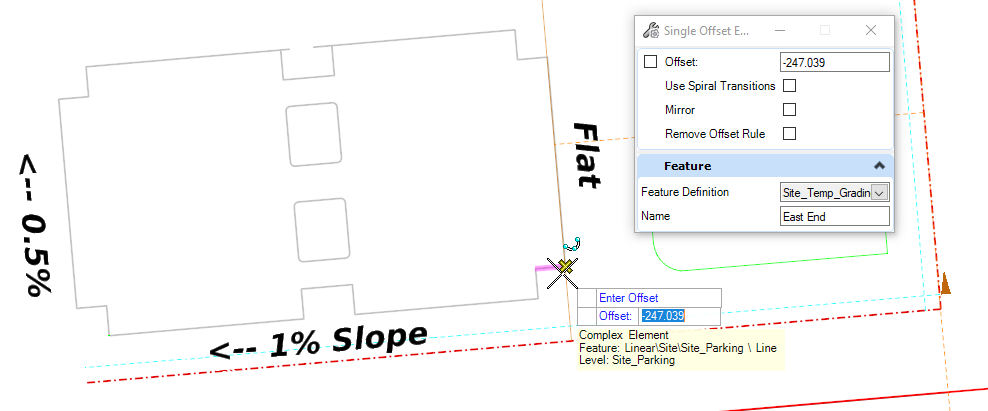
5) Do Not Mirror.
Repeat this process for the West parking boundary.
Add Profile Geometry to the east and west parking bounaries
Is the west side 1% down from the east side or is the east side 1% up from the west side? They sound equivalent, but they're not. What is your Design Intent?
It is implied from the problem statement that the west side elevation is dependent on the east side. We'll proceed in that manner. The dependent side WILL be defined via the Profile By Slope from Element tool. The "independent" side - the east side - can be defined any number of ways: whatever the engineering dictates.
The elevation of the lot is probably not actually independent.
- The side nearest the building pad might be related to the building pad elevation - either by a vertical offset below or a slope from
- The center or an edge might want to start as some value relative to the surface.
However you set the initial relationship, it is easily editable and updates are automatic. What-if scenarios and optimizations are very easy.
For this exercise, we'll use the elevation of the terrain at the center of the eastern boundary line. It's a reasonable starting point; we can change this easily later.
1) Since we're deriving a profile from a terrain,click the Geometry > Vertical > Profile Creation > Profile from Surface tool.
2) Set the tool settings as shown below:
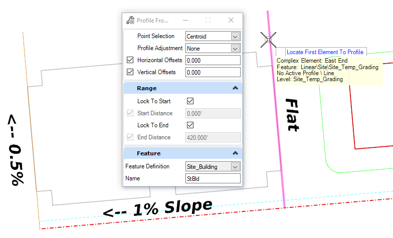
3) At the Select Element to Profile prompt, click on the East side boundary.
4) At the Select Next Element prompt, Right-click to reset.
5) At the Locate Reference Surface prompt, click the existing terrain.
6) Set the start and end of the profile along the east line - ensure that it encompasses the full footprint of the parking lot.
7) Confirm the settings with dataponts.
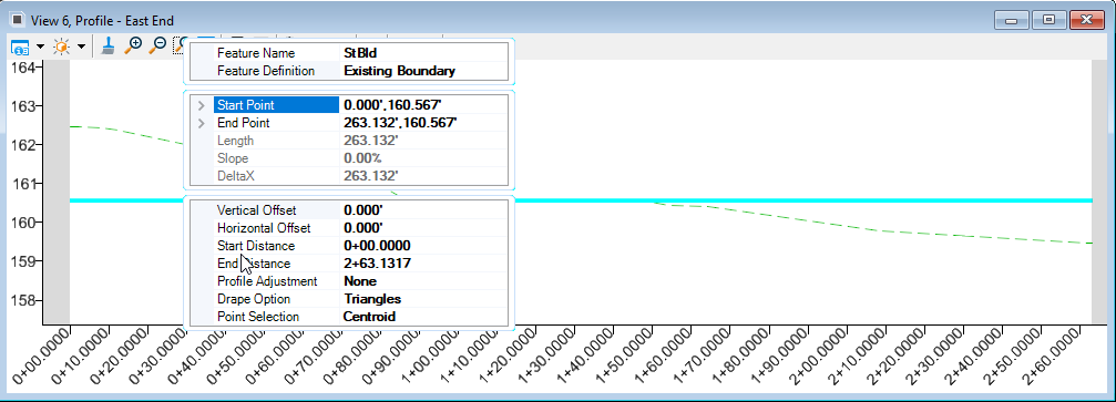
Upon completion, the profile is created and the new profile element is set active. The 3D result is shown. Note that not all the tools will set the new profile as Active.
8) Review the east side profile model:
Set the West Side Boundary at -1% from the East Side Boundary
Once the East side has an Active Profile, then we can define the dependent side.
1) Open the Profile Model for the West Boundary line.
2) ClickProfile By Slope from Element.
|
Since the East Side is level, it only has one elevation. The Resultant Profile will be level as well. Point Selection and Profile Adjustment Modes yield the same result. 3) Set the Slope to -1% (Negative is down). 4) At the Select Element to Profile prompt, click on the West side boundary. 5) At the Select Next Element prompt, Right-click to reset. 6) At the Locate Reference Element prompt, click the East Boundary line. 7) Confirm the remaining settings with dataponts. |
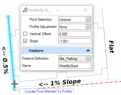 |
The new Profile is added to the West Boundary Profile Model, but it is NOT set as Active Profile.
8) Manually, Set the New Profile as the Active Profile.
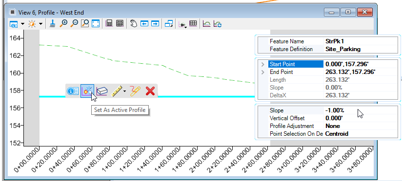
Now we have two lines in 3D. These are then used to create the Draping Terrain.
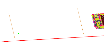
Creating the Draping Terrain from the two Profiles
Video: Creating the Warp Surface.mp4
1) Use Terrain > Create from Elements to create a terrain.
Feature Type: Break Line
Edge Method: None.
Feature Definition: Proposed Drainage Contours
Name: Draping for Parking.
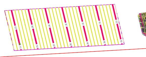
This is a better "QC" Contour and Triangle Display:

Draping the Parking Features
Video: Draping the Parking Features.mp4
Now we can "Drape" the Parking Lot Features to the "Draping Terrain".
We will use Profile from Surface again, this time selecting the Draping Terrain instead of the existing terrain.
1) Create a Selection Set of all the Parking Features - we have one perimeter and two islands.
2) Click Geometry > Vertical > Profile Creation > Profile from Surface.
3) Set Profile Selection to All
4) Set Profile Adjustment to None.
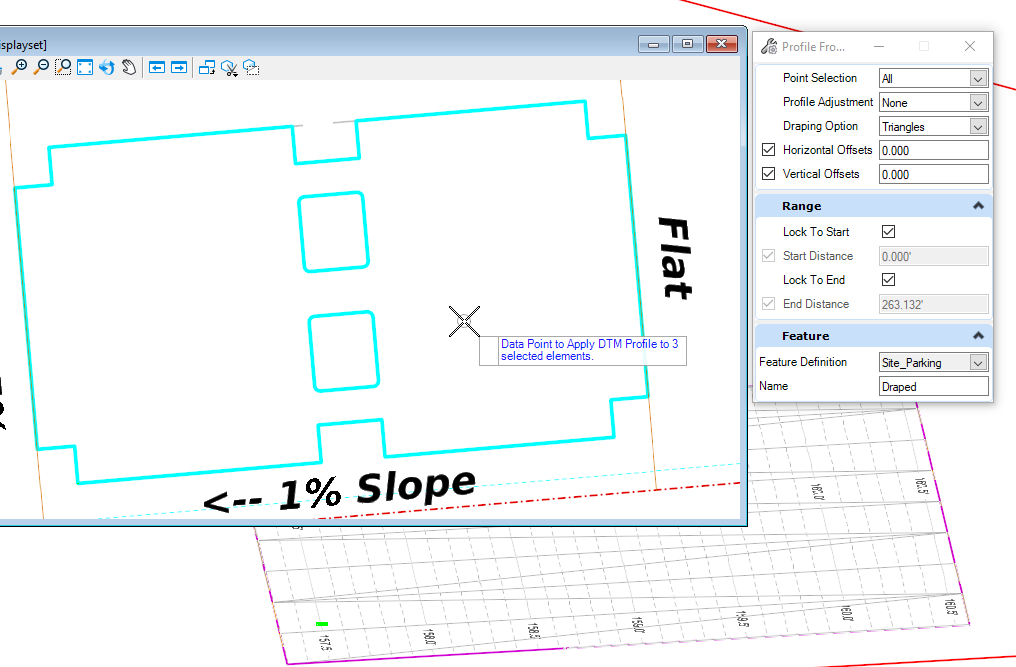
5) At the Data Point to Apply DTM Profile prompt, place a Data Point.
6) At the Locate Reference Surface prompt, click on the Draping Surface.
7) Define the Start and Stop Distances (<Alt> will lock to the Begining and End of the Element)
8) Confirm the remaining setting with Data Points
The Profile is created. If it is set to Active, you will see the elements in the 3D Model
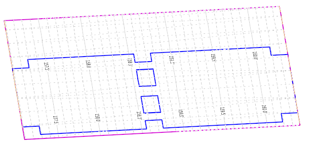
If you do not see the 3D parking, Review the Profile Model of any missing or partial elements.
Now for the Warp
Video: Warping the Parking.mp4
So far, we have the flat east side, the 1% slope to the west, but we haven't added the slope along the west curb - we don't want a flat curb ponding water.
1) First, we need to Open the Profle Model of the West Draping line.
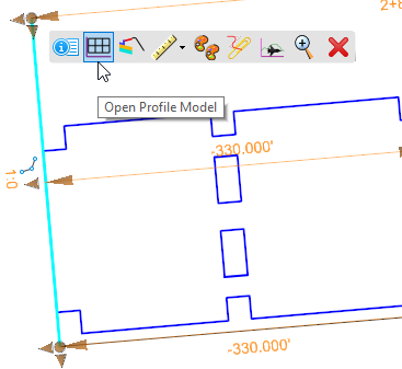
The Profile Model shows the Active Terrain Profile; the other Profile Element is the Active Profile: the Profile created from the Profile By Slope (-1%) from the East Draping line. Note its properties, which are editable.

When the Profile View is active, its horizontal parent is highlight and the direction indicated. The arrows indicate that the element starts from the south and heads north. We will want to have the grade flow from south to north: negative 0.5% from start to finish.
We will snap to the Design Profile: snaps are relationships, and we want to maintain that 1% cross slope relationship to the east side.
2) Click the Profile Line Between Points tool from the Profile View toolbar

3) Snap to the left end of the Proposed Profile (not the terrain profile).
4)Lock the Slope to -0.5%
5) Snap to the end of the profile window - the end station is snappable.

6) Right-click to end.
7) Use the Selection tool to verify the snaps (beginning and end) and the Slope.

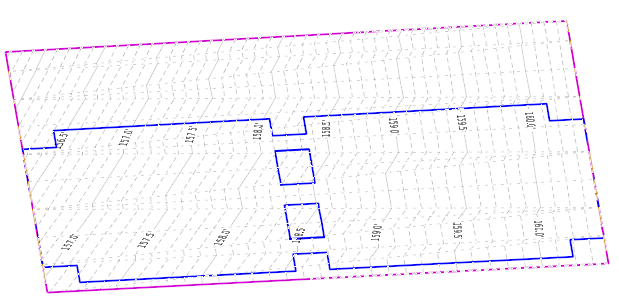
As soon as the sloped Profile is made Active, the Draping Terrain automatically updates. The Parking Elements are draped to the Draping Terrain: their profiles are automatically updated.
Troubleshooting and Followup
The finished design file is here: Parking Warp - COMPLETE.dgn
Set a Mark.
Change some of the settings in the Profile.
Change the settings over in the East Draping Line Profile.
It's all connected. OpenRoads remembers your Design Intent.
Undo To Mark if you need to.
If the Parking Lot elevation needs to be derfined relative to, say, the Building Pad elevation, you can use the Profile By Slope from Element tool to define that relationship. Changing the Pad elevation will change the Parking elevation.
The Elements of the Draping Terrain and the Draping Terrain itself are generally NOT printed. Using appropriate Feature Defintions tend to segregate those elements over to non-plotting levels and outside of the scope of quantity objects. Deleting them generally is not necessary - and doing so can break the automatic and easy updateability.
Manage complex grading sequences is generally managed via the Complex Terrain technology. Search for "Create Complex Terrain".
